At the Google I/O 2022 conference, Google Cloud released AlloyDB, a cloud-native database compatible with the PostgreSQL standard (note: “Alloy” means an alloy of metals). It claims to be twice as fast as Amazon’s competing product (Aurora?), a slogan that probably isn’t enough to convince existing users to migrate, but does hold some appeal for new users.
Since the author mainly works on storage, this article will analyze the AlloyDB storage layer architecture based on Google’s blog post introducing it, to see what highlights its design has to offer.
Overall Architecture
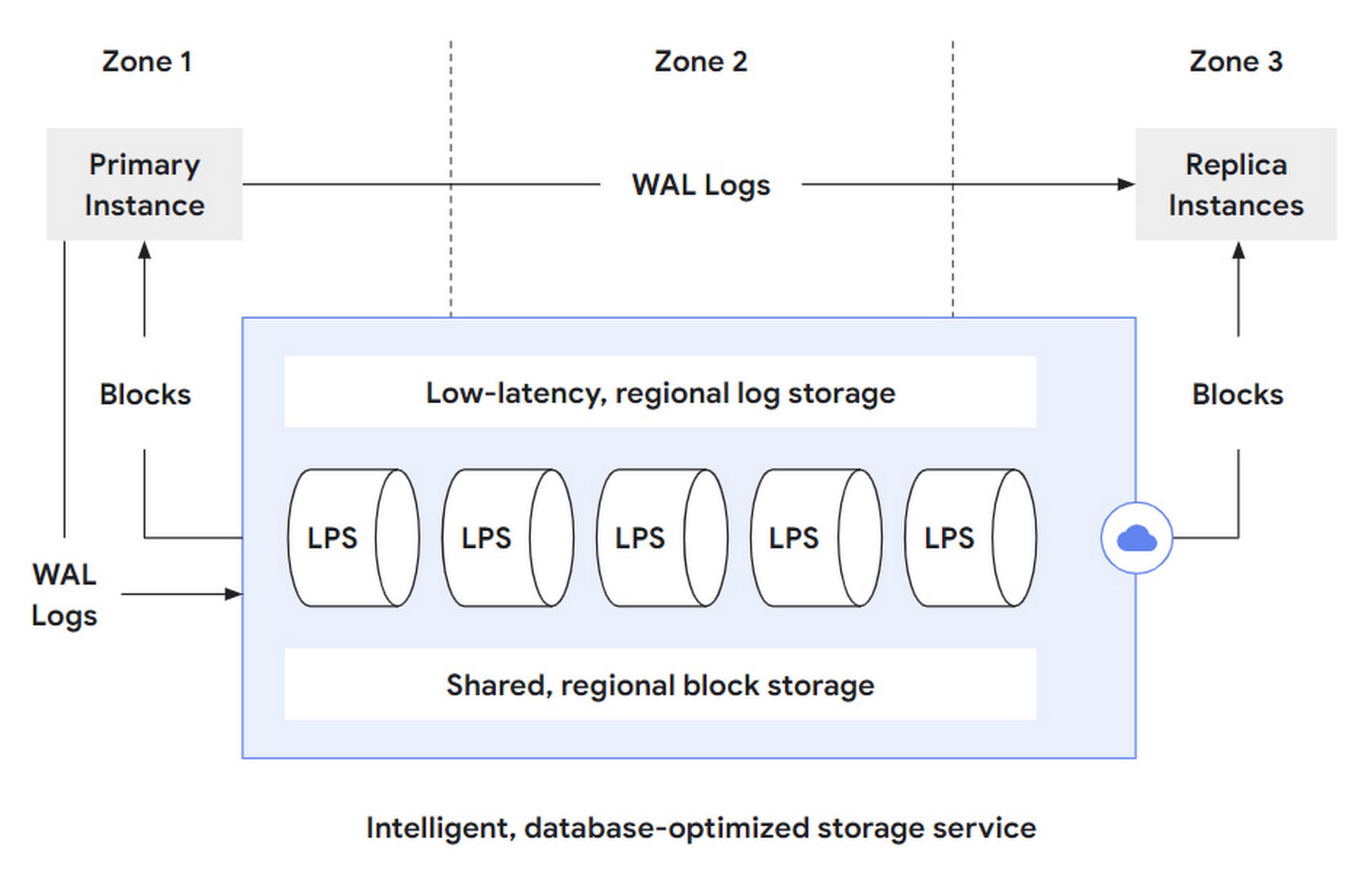
Overall, AlloyDB is divided into a Database layer and a Storage layer. The DB layer is responsible for being compatible with the PostgreSQL protocol, parsing SQL statements, and converting them into read/write requests sent to the storage layer. The storage layer can be further subdivided into three layers:
- log storage layer: The DB layer converts writes into operation logs, or WAL, which are written to the storage layer. Log storage is responsible for the efficient writing and storage of these log records.
- LPS layer: Log Processing Service, LPS, is the log processing service layer that consumes WAL from the log storage layer and generates Blocks. Essentially, it is a materialization process.
- block storage layer: Corresponding to the block layer of a standalone PostgreSQL instance, it serves queries, provides parallelism through sharding, and guarantees cross-zone fault tolerance through replication.
作者:木鸟杂记 https://www.qtmuniao.com/2022/05/15/google-alloydb-storage 转载请注明出处
 database-storage.png
That is, AlloyDB further splits its storage layer into two storage layers and one compute layer to break down complexity:
- The log storage layer handles write requests coming from the DB layer. It only supports append-only writes, so it can achieve low latency and high availability, and can use LSN for read/write concurrency control and distributed transactions.
- The block storage layer handles query requests coming from the DB layer. Although not mentioned in the article, one can guess that the blocks it provides only support write once, then become immutable, to facilitate caching and version control.
- The LPS layer acts as a data mover between the two sub-storage layers, and is also responsible for block generation and reading. It is stateless and scalable. It can dynamically add or remove instances based on various signals such as load and statistics to track changing workloads.
The storage layer essentially needs to provide block read and write services. AlloyDB splits out the log storage layer to handle writes and the block storage layer to handle reads. Implementing the storage layer based on log service materialization is considered a classic (even old) architecture in the distributed database field, but how to combine it efficiently still tests engineering capabilities.
Another benefit of being log-based is that the same data can be materialized in different ways to support different workloads, such as on-demand materialization into data formats optimized for TP and AP, that is, supporting HTAP.
Read/Write Flow
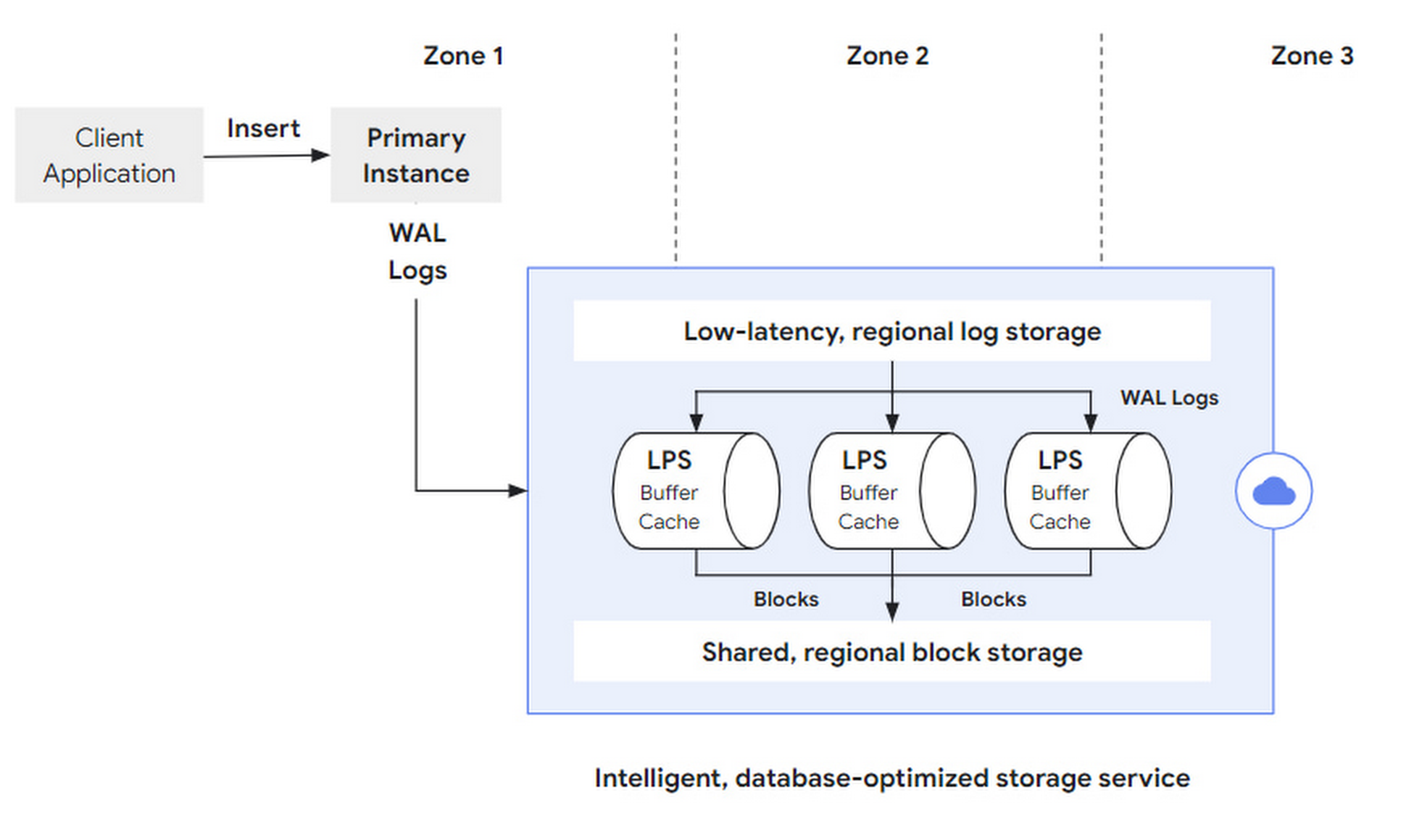
Write requests (such as SQL insert) are initiated by the client to the primary instance. After being parsed by the DB layer, they become a set of WAL Records sent to the storage layer. After WAL is synchronously written successfully, the transaction commits and returns successfully. Afterwards, LPS asynchronously materializes the logs into Blocks.
 write-workflow.png
The original article did not elaborate, but how to segment and provide fault tolerance for logs, how to deploy across multiple regions, and how to manage the log lifecycle are also critical design points.
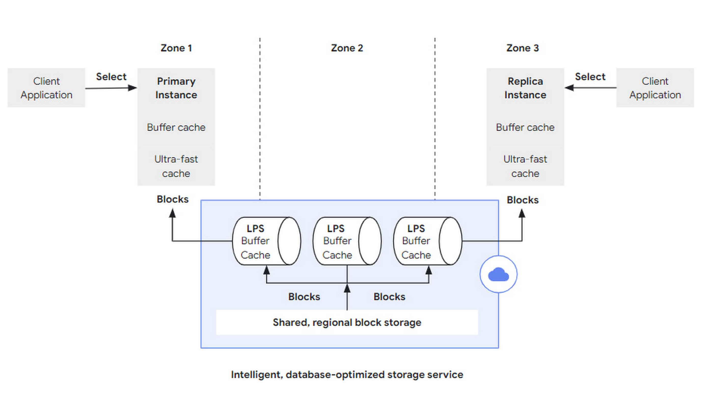
Read requests (such as SQL query) are initiated by the client to any instance. After being parsed by the DB layer, if the data hits the cache in that DB layer (Buffer Cache), it is returned directly; if the requested data is not sufficiently cached, it can be fetched from a larger, second-level-cache-like Ultra-fast Cache. If it hits there, the storage layer still does not need to be accessed.
If the required block is still missing from the Ultra-fast Cache, a block read request will be sent to the storage layer with block id and LSN:
- The block id is used to retrieve the block.
- The LSN is used to wait for LPS apply progress to ensure a consistent view.
 read-workflow.png
In the storage layer, LPS is responsible for block reads and writes. Each LPS maintains a Buffer Cache. This term is quite interesting:
- Buffer is generally used during writes to merge multiple writes together to improve write throughput.
- Cache is generally used during reads to bridge the access speed gap between different media to reduce latency.
Here, the two are combined into one. When LPS performs log apply, it first writes to its own Buffer Cache. At this time, the Buffer Cache acts as a buffer to batch flush into block storage. Before LPS flushes the Buffer Cache to block storage, if it receives a block read request and the Buffer Cache is hit, it can return directly. At this time, the Buffer Cache acts as a cache.
Of course, LPS needs to maintain data structures similar to a dirty table for the Buffer Cache to track the lifecycle of each block and when it should be flushed.
Elastic Scaling
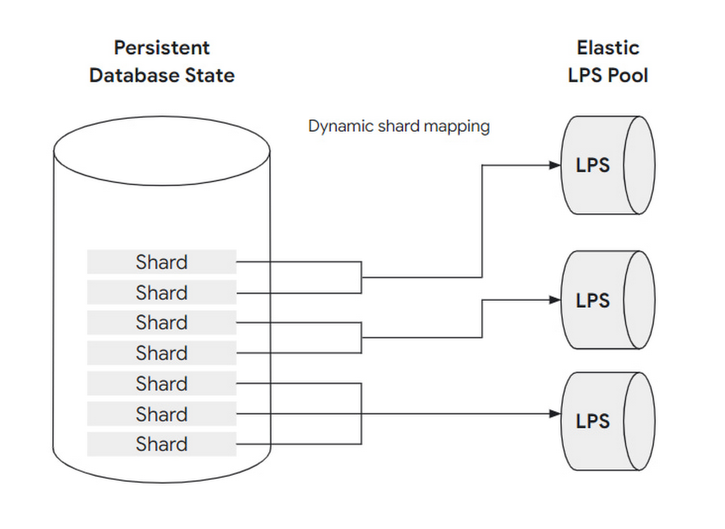
To cope with changing workloads, the number of LPS instances is designed to be scalable: that is, adjusting the mapping relationship between LPS and block shards. Before further explaining how to scale, let’s first clarify the concepts and relationships of block, shard, and LPS instance:
A set of blocks is grouped into a shard. A shard is processed by at most one LPS instance, but one LPS instance can process multiple shards simultaneously.
Using a restaurant as an analogy: blocks can be understood as guests, shards as dining tables, and LPS instances as waiters:
- When the load is low, only one waiter is needed to serve all the guests at all tables in the restaurant.
- When the load is high, at most one waiter can be assigned to each table.
This dynamic adjustment can be fully automated without user awareness or intervention. Also, because LPS has no state (Buffer Cache doesn’t count as state—think about why), it can scale quickly.
 LPS-shard.png
Cross-Zone Multi-Active
To tolerate regional failures, AlloyDB places multiple replicas of each block shard in different zones.
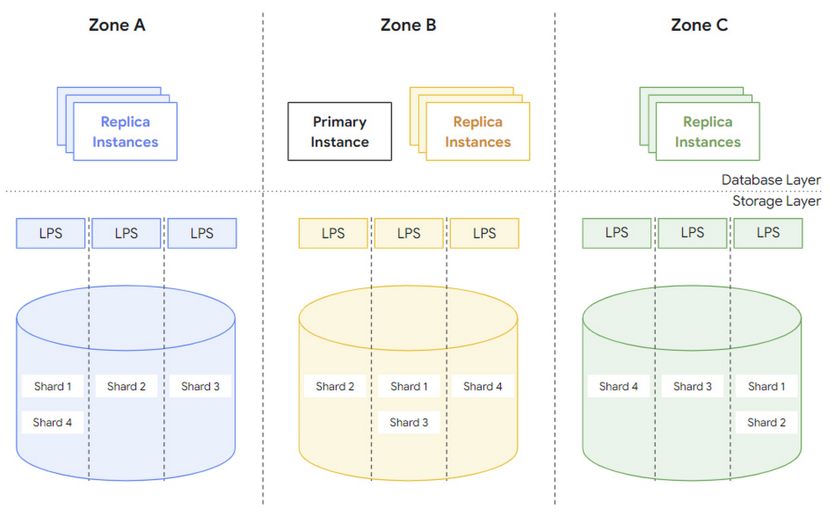 zones.png
The article mentions two concepts, region and zone. Without verifying, I guess region refers to a physical region and zone refers to a logical zone. When a zone fails, a new zone is spun up in the same region and data recovery is performed:
- First, use snapshots from other replicas to recover.
- Then replay the WAL after that snapshot.
Under normal circumstances, each zone can serve independently without too much cross-zone traffic.
In addition, AlloyDB also supports manual and automatic backups at the logical level (such as for a particular database) to prevent users from accidentally deleting data.
Summary
AlloyDB’s storage layer is implemented based on a log service, divided into two storage layers—log storage and block storage—and one compute layer, LPS. It uses LSN to control concurrency and dynamically scales LPS to cope with workloads.
What do you think of this design? Feel free to leave a comment and discuss.